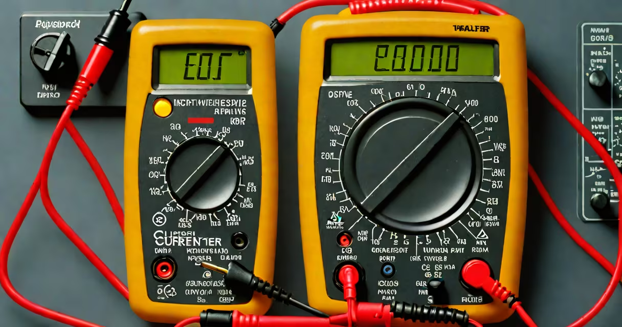
Checking current with a multimeter means measuring the flow of electric charge through a conductor using the device's ammeter function. This requires breaking the circuit and inserting the meter in series with the load, not in parallel like voltage readings.
Most digital multimeters have a dedicated current setting labeled "A" (ampere) with ranges such as 200 mA, 10 A, or auto-ranging. To measure current, you must connect the red probe to the appropriate current port-usually marked "A" or "10A"-and the black probe to the COM port. The circuit must be powered off during setup to avoid damage.
For example, when testing a 12V LED strip drawing 150 mA, set the dial to 200 mA. Turn off power, disconnect one wire from the positive terminal, insert the red probe into the wire's broken end, and the black probe into the positive terminal. Power on the circuit. The display shows ~150 mA. If the reading exceeds the selected range, the meter may show "OL" or beep-indicating overload.
The multimeter measures current by allowing the current to pass through its internal shunt resistor. The voltage drop across this resistor is proportional to the current flow. The meter calculates and displays the value in amperes (A), milliamperes (mA), or microamperes (μA).
Unlike voltage, which is measured across two points, current must be measured in series. Placing the multimeter in parallel while checking current creates a short circuit. This can blow the fuse, damage the meter, or cause a spark. A single mistake in probe placement leads to immediate failure.
Modern multimeters often include a blown fuse indicator. If the meter fails to read current and shows "0.00" or "OL," check the fuse. Most models use a 10A fuse for high-current measurements and a 200 mA fuse for low-range work. Replacing a blown fuse requires opening the case and installing a 10A or 200 mA fuse-never use a higher-rated fuse.
There are two main types of current measurement ports on multimeters: the common COM port and the dedicated current input port. The COM port connects to the black probe. The red probe must go into either the "A" port (for low current) or the "10A" port (for high current).
| Port Type | Max Current | Use Case | Risk of Damage |
|---|---|---|---|
| A (low range) | 200 mA | Small circuits: LEDs, sensors, microcontrollers | High-overload causes fuse blow |
| 10A (high range) | 10 A | Large loads: motors, heaters, battery packs | Low-designed for high current |
Using the wrong port is a common error. Connecting a 5A motor to the 200 mA port results in a blown fuse. Always verify the expected current before selecting the port. For unknown loads, start with the 10A port and switch to the lower range if the reading is under 200 mA.
One frequent error is leaving the probes in the current ports when measuring voltage. The multimeter's internal resistance is very low in current mode. Measuring voltage across a live circuit with probes in the "A" port causes a short. This can destroy the meter or trigger a circuit breaker.
Another issue is failing to turn off power before connecting the meter. Even a brief connection during power-on can cause arcing, especially in high-voltage systems. Always disconnect power, verify with a voltage tester, then reconnect the meter in series.
I once tested a 24V DC motor with a Fluke 87V multimeter. I had the red probe in the 10A port, but the motor drew 3.2A. The meter showed "3.20" correctly. When I switched to the 200 mA port, it immediately displayed "OL" and beeped-the fuse blew. I replaced it with a 10A fuse and reset the meter. After that, I always double-check the port before powering on.
"Check current multimeter" is not the same as measuring voltage or resistance. Voltage is measured across two points; current is measured through a single path. Confusing these functions leads to incorrect readings and equipment damage.
It's also not the same as using a clamp meter. Clamp meters measure current without breaking the circuit-just by clamping around a wire. They're safer for live circuits but less accurate for low currents. A multimeter requires physical disconnection, making it better for precise lab work.
Some users think they can measure current by touching the probes to a live wire. This is dangerous and invalid. Current flows through a closed loop. Touching one probe to a wire and the other to ground creates a path-but not through the intended load. The reading is meaningless and risks shock or fire.
Electricians use multimeters to verify current draw in circuits. A technician installing a 12V fan in a server rack checks the current to ensure it stays below 0.5A. If it draws 1.2A, the fan may be faulty or miswired.
Home hobbyists test battery-powered devices. A Raspberry Pi project drawing 120 mA from a 5V supply should show ~0.12A. If it reads 0.5A, there's a short. The multimeter identifies the fault before it drains the battery or damages components.
Manufacturers test production lines. A batch of USB chargers should deliver 2.4A at 5V. Using a multimeter, engineers confirm each unit meets specs before shipping. Without this step, defective units reach customers.
For AC current, the process is similar but requires the meter to support AC amperage. Most digital multimeters handle AC current in the same way as DC-select the "A~" setting, choose the range, and connect in series. However, AC current varies over time. The meter displays RMS (root mean square) values, which represent effective power.
To check AC current, follow the same steps as for DC. Set the dial to "A~" and select a range above the expected current. Break the circuit, insert the meter, and power on. A 120V AC lamp drawing 0.6A should show ~0.60A RMS. If the reading fluctuates wildly, the circuit may have noise or a loose connection.
Always verify the meter supports AC current. Some basic models only measure DC. Refer to the manual or label. A Fluke 177 has AC current capability; a cheap $10 model may not.
If you're checking AC current in a household circuit, use caution. Live wires carry 120V or 240V. Only proceed if you're trained. Use insulated probes and wear safety gear. Consider using a non-contact voltage tester first to confirm the circuit is dead before working.
Understanding how to check current with a multimeter prevents damage, ensures accuracy, and improves safety. Always match the port, range, and circuit configuration to the task. A single error can ruin a meter or harm a person.